

Traditionally, busbars are the power distribution systems that carry and distribute electricity throughout industrial premises.
In offices, the term “busbar” usually refers to a type of powertrack that’s typically installed within raised access floors and used to supply power to floor boxes beneath desks and workstations.
On this page, we cover underfloor busbars, and explain:
Click on a link to jump to that section:
Read our main floor power guide
Floor power—understanding floor boxes, busbars and underfloor accessories
The type of busbar seen in many offices is a power distribution system. It looks like a metallic track featuring a series of plug sockets that are used to feed the building’s mains power to wherever electricity is needed—whether that’s floor boxes, electrical sockets or other outlets.
Busbars both ground and conduct electricity, to safely distribute electric power throughout premises.
You can find powertrack-style busbars in:
Overhead busbars fix to ceilings or walls, while underfloor busbars sit inside the cavities in raised access floors.
The term “busbar” can also refer to large uninsulated metallic strips employed in industrial applications to distribute local high-current power. These are used in high-voltage electrical switchyards or in battery banks, for example. To prevent people touching these fatally high-voltage busbars, they are usually placed within an earthed metallic enclosure or high out of reach.
On this page, we focus on the underfloor powertrack type of busbar.
Busbars carry power from the transformer to the low-voltage switchgear—in other words, the switches, fuses or circuit breakers that control, protect and isolate the electrical equipment.
In a typical office building, the busbar system is installed under the raised floor. Its feed unit is connected to the building’s mains supply. Rooms can feature several busbars depending on the size of the room to which they are supplying power. The tracks contain strips (often made of copper) with excellent conductivity, housed within metallic trunking.
At each point where the electricity needs to branch off to power the floor boxes or other outlets above, a tap-off unit is connected. The systems tend to be designed to accept tap-off units at certain intervals, so they can be removed or added without the need to isolate the whole system.
This is one of the main advantages that busbars have over normal cable distribution systems. With cabling, you’re restricted to tapping electricity from just one fixed point. Tap-off units allow you to draw power from a number of electrical connections, and vary them as needed.
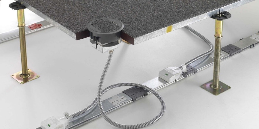
This image shows a CMD Betatrak busbar installed under a raised floor.
The two white components are the tap-off units, the first of which is connected to a floor grommet.
Busbars have come to replace cabling as the power distribution system of choice as they have a wide variety of benefits. But what makes them so advantageous, particularly to office-based businesses?
Benefit | Reason |
|---|---|
They use space more efficiently |
|
They are a cost effective solution to traditional cabling methods and less time-consuming to install |
|
They offer a more flexible range of configurations |
|
They are suitable for installations with a high ambient temperature |
|
They can be installed in long runs within the installation |
|
They require fewer additional components | Powertrack systems don’t have the same reliance on other equipment (such as cable trays etc.) to achieve a compliant installation |
Most modular busbar systems follow similar methods of installation. Below, we explain how a CMD Betatrak underfloor busbar would be installed in an office with a raised access floor.
For the best possible layout, we advise arranging the Betatrak busbars in parallel lines, with the feed units facing towards the incoming supply.
Space each length of track no more than five metres apart and no more than 2.5 metres from the nearest wall when using a standard three-metre tap-off to a floor box.
This is the standard process for installing CMD’s powertrack busbar. The process for other similar busbar systems might differ slightly.
Use a chalk string (or equivalent) to mark out where you intend the track to run. When installing, align the track lengths with the chalk line.
Note: Tighten the screw terminals for the supply cable to a torque setting of no more than 2.5Nm.
Flexible corners are made up of:
Secure both feed units to the slab.
Floor power—understanding floor boxes, busbars and underfloor accessories
Floor boxes—their features and how they can benefit your business premises